The process flow diagram for MeOH production is illustrated in Fig. CO 2 and H 2 feed streams, S1 and S2, are compressed to 78 atm, mixed with a recycle stream, S11, preheated and sent to the reaction unit (Unit 11). The reactor outlet, S14, is divided into two streams, S15 used to preheat the reactor inlet, and S16 used to preheat the column feed.
WhatsApp: +86 18037808511
Figure 1 shows the simple process flow diagram for the methanol production from the reforming of natural gas. CO + 2H2 ... size on the methanol production cost using coal and biomass as the feedstock. The study concluded the coal gasification to be more economical compared to the biomass or biomass‐coal feedstocks. ...
WhatsApp: +86 18037808511
Methanol can be produced from any feedstock that contains carbon such as natural gas, coal, biomass, and CO 2. Methanol production from syngas. About 90% of methanol production is currently from natural gas, and other technologies cannot be substituted on an industrial scale according to undesirable efficiency.
WhatsApp: +86 18037808511
Figure 2 The hierarchy process flow diagram of the integrated cleancoal technology with ... Then the methanol production from coal may be one of the best options for filling the gap because of the steady and low cost of coal and its impact on the national energy security. Using coal as the feedstock will
WhatsApp: +86 18037808511
process for the production of 5,000 MTPD of chemical grade methanol. Economics are then compared with the economics of producing 5000 metric tons per day of methanol from a
WhatsApp: +86 18037808511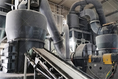
The coaltomethanol process used for this project typically incorporates the following process operations, shown in Figure 1. 4 Fig 1. Block diagram of coaltomethanol process. First, coal is preprocessed by methods such as crushing, sizing and drying to prepare it for the coal gasification process.
WhatsApp: +86 18037808511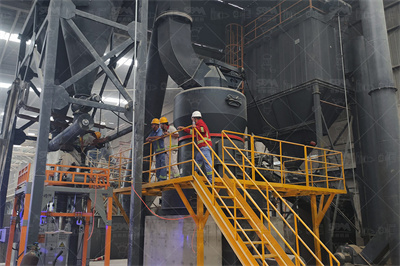
The process flow of Route 3 is similar to that of Route 1 . Route 3 uses a coelectrolysis unit and a MeOHsynthesis unit. In the coelectrolysis unit, steam and CO 2 are reduced to syngas by the SOEC after pressurization (up to ~ MPa). The syngas is then sent to the methanolsynthesis unit and converted to MeOH.
WhatsApp: +86 18037808511
In this work, a BFGtomethanol plant was simulated using Aspen Plus V10 based on the process flow diagram presented in Fig. process route was selected based on recommendations available in the literature about various aspects of conditioning BFG and methanol synthesis using either industrial syngas or CO 2 + H operations were selected with high enough TRL to be deployable at ...
WhatsApp: +86 18037808511
Download scientific diagram | Process flow diagram of methanol synthesis. from publication: 305726 Simulation and Modeling of a Radial Flow PseudoIsothermal Methanol Reactor for a More Efficient ...
WhatsApp: +86 18037808511
In 2010, the LPMEOH™ process was licensed to Woodland Biofuel Inc., with intent to use the technology to develop a woodgasification process to produce methanol from woodscrap. Figure 1: LPMEOH™ Reactor and Reaction Schematics Figure 2: Simplified LPMEOH™ Process Flow Diagram Figure 3: Simplified Block Flow Diagram for IGCC/MeOH Co ...
WhatsApp: +86 18037808511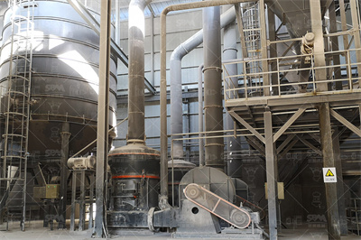
Abstract This study presents design considerations and an evaluation of a fullscale process chain for methanol and advanced dropin fuel production derived from lignite/solid recovered fuel (SRF) feedstock.
WhatsApp: +86 18037808511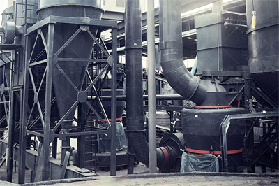
In the process simulation, two reactors were employed due to low conversion of the CO 2 hydrogenation reaction. Figure 1 represents the process flow diagram of methanol production via CO 2 hydrogenation (Wiesberg et al., 2016).In this process, the feed of 1,000 kmoles per hour of carbon dioxide at 40°C and 20 bar was mixed with the 3,000 kmoles per hour of hydrogen (at the same conditions).
WhatsApp: +86 18037808511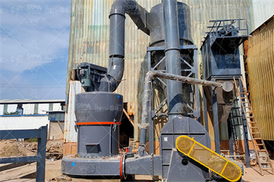
Similar to the FT reaction, the reactor has a shell and tube heat exchanger where the coolant is circulated through the shell, and catalyst particles are packed into the tubes where the reactant/product liquids flow. Figure shows a schematic of the methanol synthesis process. Figure : Schematic of the methanol synthesis process.
WhatsApp: +86 18037808511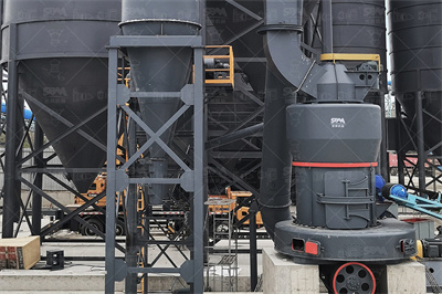
The Purisol process coupled with Claus sulfur recovery is used for the processing of syngas. Further, the WGSR is used to maintain the ratio of carbon monoxide to hydrogen. A process flow diagram for the production of methanol from coal is depicted in Fig. Chen et al. suggested a simulated model for the production of methanol from coal [15 ...
WhatsApp: +86 18037808511
iii Abstract Methanol synthesis has been the subject of many improvements over the last decades since it became more cost effective and scalable than earlier high pressure technology.
WhatsApp: +86 18037808511
The block flow diagram of the CO 2 hydrogenation option for methanol production ( CCUmethanol) is shown in Fig. 4. In this option, the feedstock is a mixture of CO 2 and highpurity hydrogen. The carbon capture unit captures CO 2 from the flue gas, and the water electrolysis unit produces the required hydrogen.
WhatsApp: +86 18037808511
This study presents design considerations and an evaluation of a fullscale process chain for methanol and advanced dropin fuel production derived from lignite/solid recovered fuel (SRF) feedstock. The plant concept consists of a hightemperature Winkler (HTW) gasifier coupled with an air separation unit (ASU), which provides a highpurity (%) gasification oxidant agent. The concept ...
WhatsApp: +86 18037808511
Major sources of methanol production are natural gas and coal. Several types of methanol technologies have been developed by various licensors. Notable among those licensors are Lurgi, JohnsonDavy, Haldor Topsoe, Casale, and Mitsubishi Gas Chemicals. ... of process flow diagram. Process economics are presented toward the end of each chapter.
WhatsApp: +86 18037808511
Baseline Analysis of Crude Methanol Production from Coal and Natural Gas Disclaimer This report was prepared as an account of work sponsored by an agency of the United States Government. Neither the United States Government nor any agency thereof, nor any of their ... Exhibit 37 Simplified process flow diagram of coal to crude methanol ...
WhatsApp: +86 18037808511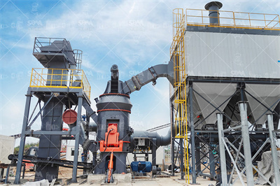
footprint of the methanol industry are growing—especially regarding the coalbased methanol production processes. An advantage of methanol is that it is a product of CO ... Figure Hydrogen production by electrolysis of water for green methanol plant—Process flow diagram 30 Figure Green methanol production—Integrated methanol ...
WhatsApp: +86 18037808511
Simplified block flow diagram of the natural gas re forming process for the methanol production. In rec en t y ear s, d ir ect hyd rog en at ion of CO 2 for methanol production has been a subject ...
WhatsApp: +86 18037808511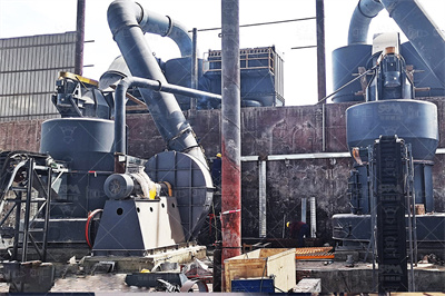
This chapter is an overview of not only common feedstocks used in the production processes for obtaining methanol (natural gases, CO 2, or char/biomass), but also of the historical production processes (such as the BASF process, also known as the "highpressure method," and the ICI process, also known as the "lowpressure method") and the most i...
WhatsApp: +86 18037808511
The FischerTropsch process is a catalytic chemical reaction in which carbon monoxide (CO) and hydrogen (H 2) in the syngas are converted into hydrocarbons of various molecular weights according to the following equation: (2n+1) H 2 + n CO → C n H (2n+2) + n H 2 O. Where n is an integer. Thus, for n=1, the reaction represents the formation of ...
WhatsApp: +86 18037808511
The ambitious CO2 emission reduction targets for the transport sector set in the Paris Climate Agreement require lowcarbon energy solutions that can be commissioned rapidly. The production of gasoline, kerosene, and diesel from renewable methanol using methanoltoolefins (MTO) and Mobil's Olefins to Gasoline and Distillate (MOGD) syntheses was investigated in this study via process ...
WhatsApp: +86 18037808511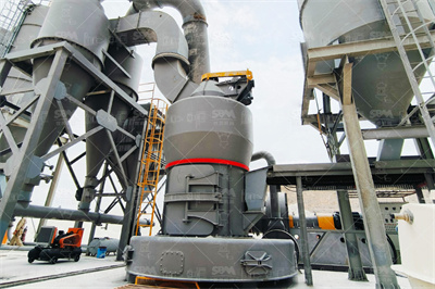
Conceptual process flow diagram of dry reforming of natural gas for methanol production Full size image Feed containing carbon dioxide and methane is preheated through heat exchange with the reactor effluent and then further heated in a furnace to the reaction temperature, 850 °C, and then fed to the fixed bed reformer (reactor 1).
WhatsApp: +86 18037808511
Methanol is a basic 'building block' for the production of other chemical products such as Plastics, Paints and ManMade Fibers. It has also found a large use in the production of Gasoline Fuel additives. How Is Methanol commercially produced?
WhatsApp: +86 18037808511
A material supplier from Belgium would like to produce limestone powder for his custome...

India is rich in various mineral resources and it is an important mineral processing market
Copyright © 2023 GMC Co., Ltd. SiteMap

